

Written - April 1997
Step 0: Lay Out the Parts
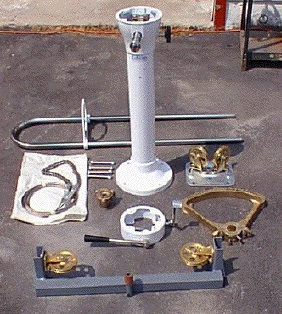 Here's a quick shot I took of some of the parts that came in the boxes from Edson. I highly recommend laying everything out and putting it together once or twice to get a feel for how the parts go together. In the process of doing so, I discovered that I had forgotten to order a few things like take-up eyes and engine control cables. (Details, details...)
Step 1: Remove the Rudder
 Like many boating projects, simple things often cascade (avalanche?) into major undertakings. In order to attach the quadrant to the rudder stock, the rudder tube must be cut. In order to safely cut the rudder tube without damaging the rudder post, the rudder should be removed so that the rudder tube is clear. On the Alberg 35, the propeller and shaft must be removed in order to drop the rudder.
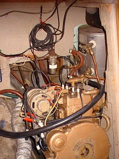
To the right is a quick shot of the engine space in the Alberg 35. The shaft coupling is (naturally) just behind and below the engine. It took two days and a supply of Liquid Wrench to remove the coupling from the engine. A gear puller didn't fit in the space provided to pull the coupling off the shaft, so some longer coupling bolts were located and small socket wrench sockets were used between the transmission and the coupling to push the propeller shaft out of the flange.
 With the propeller and shaft out of the way, the next step was to drop the rudder. To accomplish this the bronze shoe (gudgeon?) at the bottom of the keel and the retaining strap just below the propeller cutout need to be removed. The gudgeon is attached to the keel with five (5) copper drift pins that have been driven through drilled holes, peened over and faired smooth. The strap is attached similarly with two (2) pins. Each pin is approximately 1/4 inch in diameter.
The only way I could figure out to remove both pieces was to drill out the copper pins and pull the shoe and strap off. The next two pictures show the trailing edge of the keel after the strap and gudgeon have been removed.
Be sure to support the rudder so that it doesn't fall out as you remove the last pin! The original rudder is solid mahogany and it will bruise a few toes if it should fall on them. My suggestion is to remove the upper strap first. Then loop a small line, say 1/4-inch, around the cutlass bearing and through the strap cutout in the rudder two or three times. If you loop three times, this will create enough friction to prevent the rudder from crashing onto toes and fingers.
 Because the drilling done to remove the copper pins was (in my case) somewhat exploratory and haphazard, the holes were stuffed full of fiberglass and faired smooth with a grinder so that fresh holes could be drilled for the bronze bolts that will replace the pins.
You will need two different lengths of bronze bolts because of the taper in the gudgeon. Four of the five bolts can be 3.5 inches long. The fifth one should only be 3 inches long. This will save you some time if the bolts you are ordering are not threaded along their entire length.
You will need two bolts for the upper strap, each 3.5 inches long. All bolts (strap and gudgeon) will require some trimming so as to minimize drag and the odds of snagging something on the protruding bolt. Be sure to use lock washers to minimize the chances of a nut working off the end of a bolt.
Step 2: Locate the Pedestal
 Topsides, the cockpit was measured and the steering pedestal was placed in its operating position to make a final check on its placement. A few minor adjustments were made and then the deck was marked for drilling holes for the steering cables, engine controls and electric wiring.
The easiest way to mark the deck for drilling is to place the sheaves which are mounted immediately below the pedestal on the deck and then trace the hole pattern, since these holes line up with the pedestal base.
One interesting note to pass on: After measuring the cockpit sole to make sure that the steering pedestal would be centered, I took a step back and noticed that things just didn't look right. Checking my measurements again (and for a third and fourth time, too), I discovered that the original rudder post was off center by nearly 1 inch to port. Keep in mind that boats are often built such that they will go together, not necessarily so that they are symmetric!
Oh, the stripes on the deck were caused by dirt and the type of non-skid plastic grating that was laid in the cockpit.
Step 3: Prep Work Below Decks.
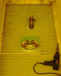
 Crawling into the port cockpit locker you can see the underside of the cockpit, the rudder tube, engine control lines and a couple of vents for the bilge and engine. Little did I realize that this locker would become my home for the better part of two days!
Below-deck preparation for the steering system includes reinforcement of the cockpit sole, the cutting of the rudder tube and the placement of the quadrant, pulleys and cables used to steer the boat.
The Alberg 35 cockpit sole consists of a balsa core sandwiched between two fiberglass layers that are each about 3/16 inch thick. A minimum amount of reinforement to consider would be 1/2 inch of plywood. 5/8-inch plywood would be even better.
 Since I was ignorant of the cockpit sole construction and could not find a suitable piece of 5/8 or 3/4 inch plywood, I epoxied together two 1/2-inch pieces, coated the exterior surfaces with epoxy, and then epoxied and glassed this structure to the underside of the cockpit sole. Having some syringes or a caulking tube full of epoxy during this operation is handy as the cockpit sole seems to have a slight crown to it in order to promote drainage. (At least mine does, so I'd like to think it was a deliberate design feature!) The syringes or caulking gun can be used to force thickened epoxy between the deck and the plywood. Four short screws were used to hold the plywood in place until the epoxy cured.
Edges of the plywood were then glassed to the underside of the deck with the exception of the edge nearest the camera so that I could continue to work in the locker without glassing myself to the cockpit sole. This last edge was glassed over at the end of the day so that it could cure overnight.
Also completed in this photo is the cutting of the rudder tube. Notice that the part of the rudder tube going through the cockpit sole is missing. After cutting the tube, I discovered that the glassed joint between the rudder tube and deck had come apart, allowing me to remove the upper part of the tube without difficulty. The rudder was pushed back into place and supported with wooden blocks and a small jack while the quadrant was fitted.
By the way, the green and yellow tints to these photos are due to the color of the plastic tarps covering the boat (see Alberg Home Page). I tried to correct the color balance of the photos, but haven't mastered the technique just yet.
 What followed was a lesson in 3-D geometry and how a drawing on paper makes perfect sense but simply won't work in real life!
For several hours, I tried to place the below-deck components for the steering system into the arrangement I had measured and visualized. Unfortunately, things simply would not align in the space allotted. Much of the trouble is caused by the fact that the rudder post is angled back at approximately 45 degrees. The rest probably had to do with the designer (me!). Add to this that gravity works well on large castings and cramped, inverted quarters work well against the stamina of human occupants.
The steel clamp around the base of the stuffing box is there to provide pressure for the fiberglass and epoxy against the casting since it is a slightly smaller diameter than the Alberg's rudder tube. The clamp was removed and a third and fourth layer of glass were applied on the following day. The top of the rudder tube was also replaced to aid in precisely aligning the rudder post, as there is very little clearance in the stuffing box.
 Finally, I found an arrangement that would work, but at the expense of losing the utility of the built-in rudder stop on the sheave bracket. Sheave alignments and cable paths were checked with a quarter-inch dowel. The upper rudder tube was trimmed to the correct length and glassed into position, the sheave bracket was bolted into place and the glass work around the stuffing box was completed. Clearance between the quadrant and the outer sheaves is approximately 1/16 of an inch. It's tight, but it should work.
One hint I can pass on to anyone working in this area of an Alberg 35 is that a towel, lump of clay or wad of duct tape should be placed along the bottom of the inside of the hull just aft of the fuel tank to stop nuts, bolts, washers, wrenches and other tools from sliding down to the bottom of the bilge when they get dropped. I measured 40 inches of clearance between the aft end of the cabin sole and the bottom of the bilge! That's quite a reach and you won't want to do it too often.
Step 4: Replacing the Rudder.
At this point in the process, the rudder could be permanently replaced. Rather than pounding in pins to remount the rudder strap and gudgeon, I decided to install silicon bronze carriage bolts that had been cut to the proper length. These were ordered from Jamestown Distributors along with the proper nuts and lock washers.
The trick to getting the rudder and gudgeon into position so that I could re-drill the holes for the bolts was a combination of a hydraulic jack and a Spanish windlass (look at the lines between the cutlass bearing and the rudder cutout for the strap). You can also see the small trench required to drop and reinstall the rudder.
After the rudder was aligned, holes were drilled through the keel using the gudgeon and rudder straps as guides. The jack was released so that the gudgeon could be dropped and lathered up with a generous helping of Life Caulk, a polysulfide sealant. The jack was then used to press the gudgeon home and the bolts were inserted and tightened. After the caulk had time to skin over the excess lengths of the bolts were cut off with a small Dremel tool. Additional Life Caulk was used to fair the surface prior to bottom painting.
Step 5: Installing the Pedestal & Cables.
Now the fun part! Thread the cables for the engine controls, steering cable, and wiring for the compass light up through the pedestal and line up the cable clamp with the pre-drilled hole so that you can insert the retaining screw. Invite lots of friends or grow a few extra arms before you attempt this!
Another hint: It seemed to go easier threading the engine controls up through the bottom of the pedestal rather than the other way around. Be sure that they are not in the path of the steering cables, as the steering cables will be under considerable tension and will chafe through the engine cable covers if they come into contact.
And yet another hint: Install the pedestal guard deck fittings before you caulk the pedestal to the deck. This will give your willing helper a place upon which to rest the pedestal without dropping it prematurely into a sea of Life Caulk.
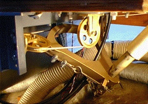 Once the pedestal is in place, the below deck components can be mounted and the bolts tightened. This shot shows the finished product after the steering cables were trimmed to length and tensioned.
Note that the engine control cables travel through the quadrant. While this is not an ideal situation, it was one that worked as the rudder does not travel far enough to deflect the cables to any appreciable degree. A tie down location for the cable will eventually be glassed into place to minimize the chafe of the transmission cable against the quadrant. Rudder stops and a strongback for the rudder tube are also being considered.
Step 6: The Finished Product.
 I figure I'll let the pictures do the talking at this point. This project turned out to be a bit more work than I expected and I'm pooped!
 The dog's name is Ruby and she has been with me for the last 10 years (as of 1997), unfortunately she doesn't care much for sailing. (Does the term "sick as a dog" conjure up the appropriate image for you?)